|
|
Post by striderider on Oct 1, 2012 15:15:18 GMT 1
Hiya all,
I'm in the thought process of creating a LED rev' counter. Consisting of 12 or so LEDS's from green (at the low rev's), to orange (mid range) & red for (near & on the limiter).
This will be modelled in the shape of a keyboard space bar & mounted on the rear-side of my fly-screen. The casing will be defussed & angled down so it lights up my handlebars
I think I've got the circuitry worked out but I need to know some critical figures.
What is the voltage readings from the live feed at the different rev ranges? (I can then get the necessary resistors to complete my idea).
Thanks all - If I can get this idea into a creation then I'll update you'll on how to make it.
oh, I forgot to mention: I don't currently have a rev counter nor a multimeter - so I'm hoping a friendly NTV'er can help me out with the figures
|
|
|
|
Post by striderider on Oct 2, 2012 15:17:15 GMT 1
I'm kinda answering my own questions, but please feel free to jump in to help out as I'm new to this electronic malarky.
I've found out that the original wireing of the Revere has a pulse output sender to the tachometer, not a voltage range as I thought.
So....Looks like I have to make a voltage regulator taking the 11.8v-13v off the main voltage feed down to a steady 6v.
Also take the pulse input run it through a frequency to voltage converter..and
Feed it to the input source of a couple of 10 way LED display drivers (to drive the 20 LED's)
Annoyingly, there used to be a product called a "Datatool RevLight" which now no longer exists which look to do exactly when I'm wanting to achieve
|
|
|
|
Post by noakira on Oct 2, 2012 17:05:35 GMT 1
Doesn't the pulse sender lend its self to an analogue clock ?
Fair play to you if you get it working though.
I've been thinking about trying to set up a Hazard lights switched on from a switch on the front of the bike somewhere.
Have you looked at Sparkbright products on ebay ?
|
|
norfolknchance
Sheene Gold rider. Nuff said
 15967 mile & climbing
Posts: 783
|
Post by norfolknchance on Oct 2, 2012 17:20:51 GMT 1
hazard lights are easy set up
|
|
|
|
Post by noakira on Oct 2, 2012 17:31:03 GMT 1
Anymore information would be appreciated.....  Currently writing this whilst being rocked about on the Shetland Island ferry Where would be the best placement for the switch and at what junction point would be best where all 4 wires cross ? |
|
norfolknchance
Sheene Gold rider. Nuff said
15967 mile & climbing
Posts: 783
|
Post by norfolknchance on Oct 2, 2012 17:32:44 GMT 1
|
|
|
|
Post by rj2para (Bisto) on Oct 3, 2012 13:51:35 GMT 1
Rather than starting all our electrickery ideas in one topic. Please can I suggest if you have a new idea, then start a new topic, rather than dilute an existing one. I suspect you will also get more responses, to you own topic if it not buried within another. Ta  |
|
|
|
Post by striderider on Oct 8, 2012 11:53:08 GMT 1
More updates on my research. It seems a few people (with circuitry knowledge & soldering skills) have already taken my idea and created their own versions: The curcuit diagram which takes the 12v ignition feed & signal pulse outputting to 2x liner/bad LED drivers looks like this: 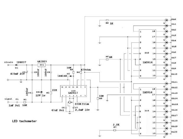 My colleagues say it's a very simple circuit, but I'm 'just' able to follow it - not sure my skills are up to it yet. Looks like I've a couple of options: Option 1:Build from stratch using the diagram from above & cross my fingers it works Option 2:Use a VU meter kit from Velleman or similar (this will keep the circuit board pre-designed & will just need to hook-up a 12v to 9v voltage regulater & frequency to voltage IC chip www.velleman.eu/products/view/?id=18696Option 3:Find someone who wants to make it for me |
|